RCA Tube Radios
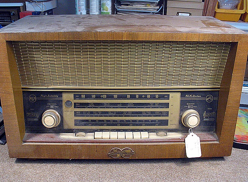
1957 RCA 9-INT-1 AM/SW/FM Table Radio by Graetz
In the 1950's, American GI's were bring home beautifully styled radios made by Grundig, Saba, Normende, Philips, and other European manufacturers. With large wood cabinets filled with woofers and tweeters, these radios were capable of high fidelity sound reproduction. The radios featured inputs for phonographs and the new reel-to-reel tape recorders appearing on the market.
RCA contracted with West German electronics manufacturer Graetz, to build the RCA 9-INT-1 for the US domestic market. A console model, the 9-INT-2, was also offered, with an RCA RP-205 record changer. Quite a few other German-built table model radios were offered by RCA in addition to the top of the line model shown here. Click here for a list of German Built RCA Radios
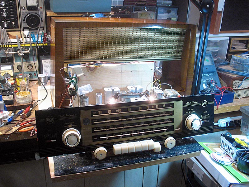
I bought this radio about ten years ago, but put off attempting restoration as I didn't feel like I had the experience needed to work on it. As it turned out, I still don't. The radio has a couple issues I was unable to resolve, even with advice from fellow members of the Antique Radio Forum. After replacing all the paper caps and electrolytic caps, checking the value of each resistor, and replacing bad tubes, including the EM34 "Magic Eye" tube, I could not get the radio to perform correctly on FM.
The audio quallity is outstanding, but the radio only receives the upper half of the FM band. I suspected an open oscillator trimmer, but it checked out OK, and did other capacitors in the FM tuner section. Whatever the cause, it has eluded me. The AM and SW bands work fine on a random wire antenna.
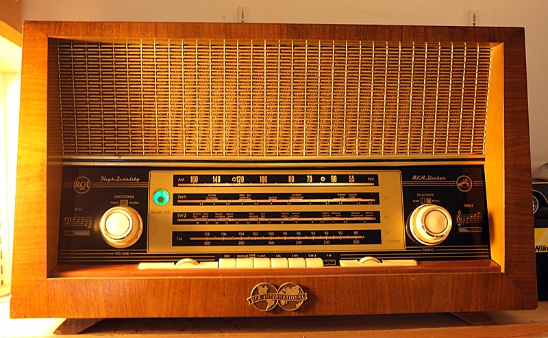
The cabinet was in very good condition, other than some crazing of the original nitrocellulose lacquer finish. This lacquer is very difficult to remove, and did not look that bad, so I cleaned it well, then applied stain to scratches and other blemished, then misted the radio with several light coats of spar urethane. The dial glass and controls were thorooughly cleaned. It turned out very nice.
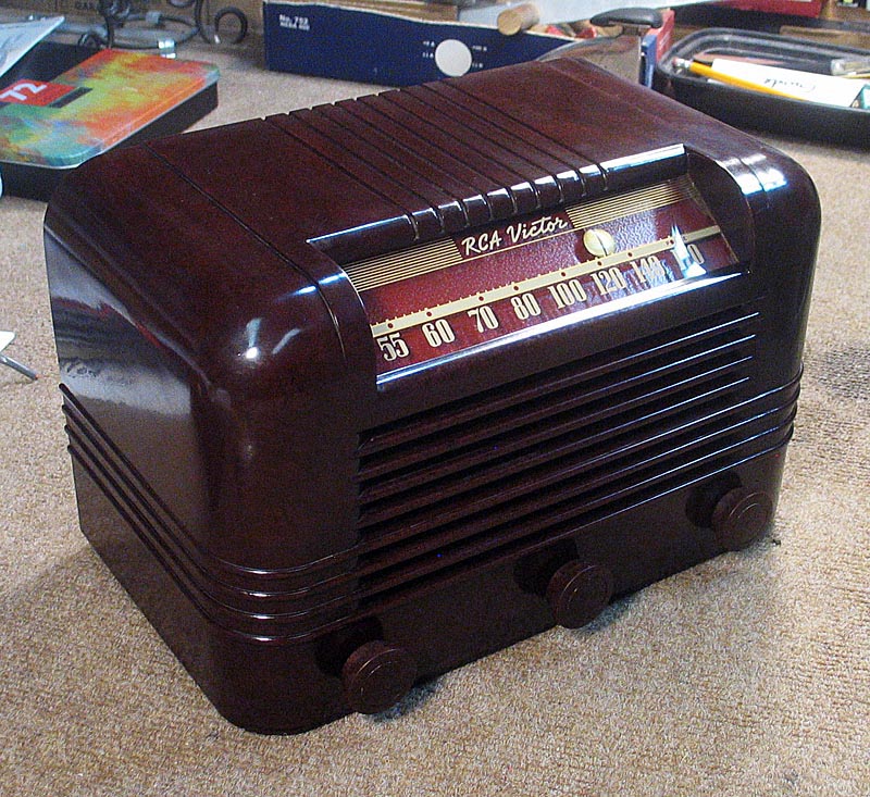
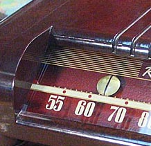
1940-1942 RCA Model 15X Table Radio
This RCA 15X sat on a shelf for about ten years before I finally pulled it down and restored it. When I got it, it was missing the red dot dial pointer. A few years ago I ran across one and bought it. The John Vassos designed 15X was one of the first, if not the first, small table radio to feature a slide rule design, which John Vassos preferred over the round airplane style dials.
When I opened up the radio, I could see that the speaker was beyond repair. The cone was so brittle, any touch made a hole. It could be re-reconed, but that's not something I have yet tried. Also the 35L6 output tube was missing, and somewhere in its past, the 12SQ7 had been replaced with a 14B6 and adapter.
I replaced the 5" speaker with a 4" speaker, which was all I had. I had to make a bracket, and I expoxied the new speaker to the bracket I fabricated and bolted it to the original bracket. It sounds good, although I don't know what the original sound quality might have been. I did the usual recap, and ended up replacing every resistor. Every one had drifted high. Fortunately there are not a lot of caps or resistors in the 15X circuit.
 I cleaned the cabinet by lightly wet sanding with 1200 grit paper lubricated with water and Simple Green. Then I buffed and polished the cabinet with Brasso. It came out pretty decent. The dial pointer I had bought some time ago had the paint worn off right in the center where it must have been rubbing against the dial cover. I didn't have the right color paint to match the original, so I ended up sanding down to the brass, and giving the pointer a coat of lacquer. It's not OEM, but I think it looks very distinctive.
The radio is very sensitive and picks up quite a few local AM stations that some of my other radios won't pick up. Sound quality is good. It has a phono input on the rear, but no phono switch, so the only way to use it is to tune to a quite spot, then kill RF by disabling the loop antenna by opening the jumper on the rear; then it sounds Ok.
My version has a two position tone control with the tuning knob in the center. The dial pointer moves in the opposite direction to the tuning knob, so the tuning knob is turned counter clockwise to move the dial from the low, or left side of the scale to the right, or high end. Kind of weird, and takes some getting used to.
The radio includes the old police band, so it tunes to 1720 KHz, which means this radio can receive stations on the expanded AM broadcast band. I picked up a station out of Charlotte, NC, at 1660 KHz, but forgot the call sign.
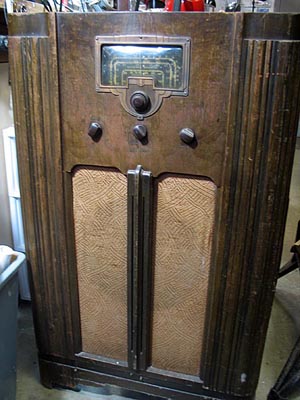
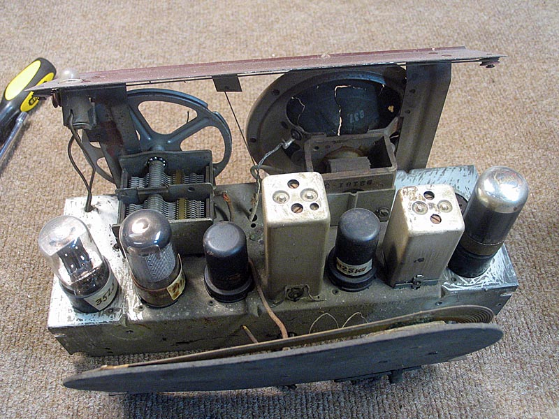
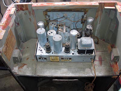
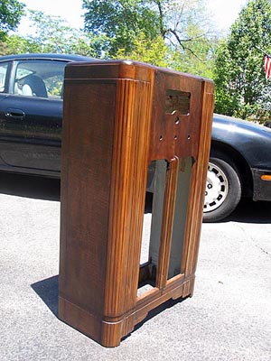
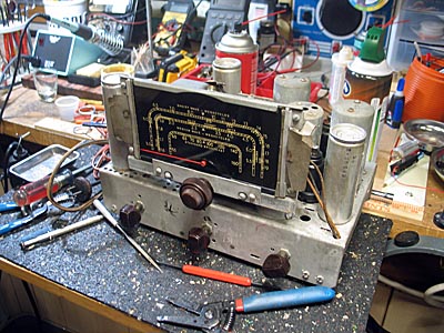
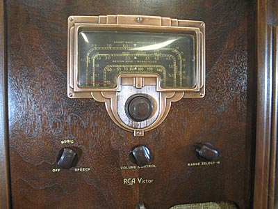
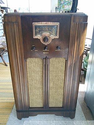
1936 RCA Model 6K2 Console Radio
This radio was given to me. Had I known at the time what I was in for, I might have have tossed it in a dumpster. While not really apparent in the photo at right, the cabinet was in very poor condition. The veneer was completely gone on the right side, and badly cracked and delaminating on the left side. The top was completely loose and begining to delaminate as well, with a couple of small pieces of veneer missing.
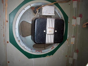
This was only the beginning. The chassis had major issues, mainly the fine tuning mechanism was broken and the broadcast band only picked up one strong local station, indicating a possible open in the broadcast section of the antenna coil. The radio picked up shortwave stations fairly well, which confirmed my suspicions about the antenna coil. Finally, the speaker turned out to have such a badly warped voice coil that I couldn't repair it.
So, in addition to a major restoration of the cabinet, I ended up having to find a parts chassis and another speaker. On the plus side, all the knobs were present. In the end, this free radio ended up as my most expensive and time-consuming restoration.
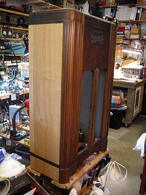
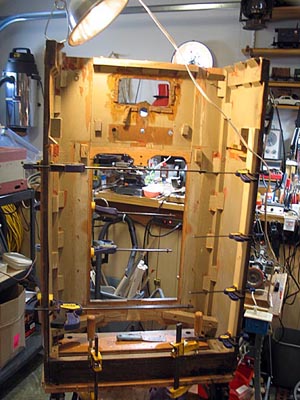
The first step in restoring the cabinet was to reglue the top piece, and reglue some weakened joints. The next step in cabinet restoration was removing the old lacquer finish. For this step, I used Minwax Antique Furniture Restorer, which removes the old lacquer while retaining the original stain. I removed all the damaged veneer from the left side, then glued new veneer to both sides. Once the new veneer was firmly attached, I went over the cabinet with matching stain to even out the coloring. I then applied multiple coats of lacquer and toner, with wet sanding between each set of three or four coats. Before the last few coats of lacquer, I applied a new set of decals to the cabinet face. I used white vinegar to remove all lacquer from the dial bezel, polished it, and then applied a new lacquer finish. I made a new speaker cloth as the original was in poor condition.
I found a chassis from an RCA 6T2 radio for sale on eBay. The 6T2 and 6K2 chassis are identical. The 6T2 chassis is from a table model radio whereas the 6K2 fits the console cabinet. The 6T2 chassis turned out to be in much better condition than the original chassis, so I ended up transferring the dial assembly from the original chassis to the parts chassis, and after recapping, and replacing some resistors, installed it in the restored cabinet, along with a new set of NOS tubes. I used an RCA 6V6 glass tube in place of the original 6K6 metal output tube as it uses less current, runs cooler, and probably sounds a little better than the 6K6.
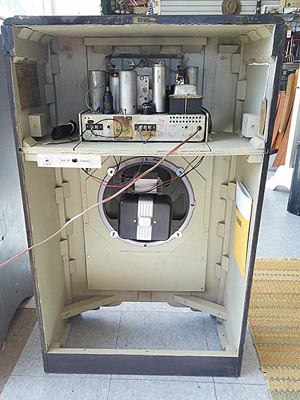
The audio quality with the original speaker was very poor, with much rattling of the speaker at lower frequencies and other distortion. This turned out to be a rubbing voice coil. I tried shimming and readjusting the spider, but the voice coil was just too badly warped. From the condition of the cabinet, I suspect the radio had been stored in damp or humid conditions for a long time. I found a 12" RCA RL-103 PM speaker from a 1948 console on eBay.
Other than lacking the field coil, the new speaker is nearly identical to the original speaker. I was able to transfer the original audio transformer to the matching mounting holes on the new speaker. To mount the bell housing, that covered the field coil, on the new speaker, I had to drill and tap new mounting holes, and use a wood spacer in place of the field coil. Since the field coil on the original speaker is also part of the radio's power supply circuit, I had to install a 1000 ohm, 10 watt resistor in the cabinet in place of the field coil.
With the new speaker in place, the radio finally was performing as it should, with good reception on all bands, and nice audio quality. For a final touch, I installed an auxilliary input jack and switch to allow the use of an external device to play audio through the phonograph tap on the rear apron of the radio.
Hear this radio play: 1936 RCA 6K2
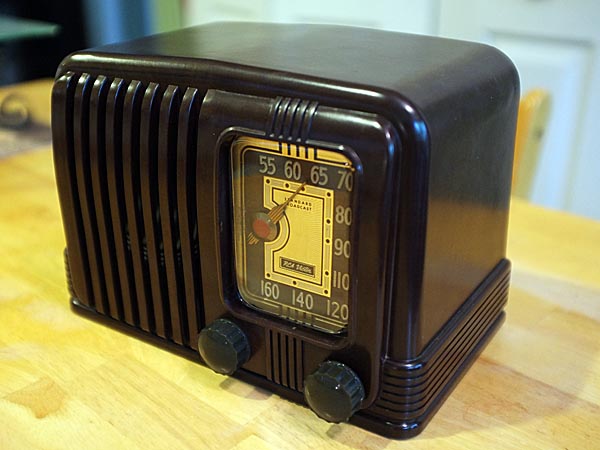
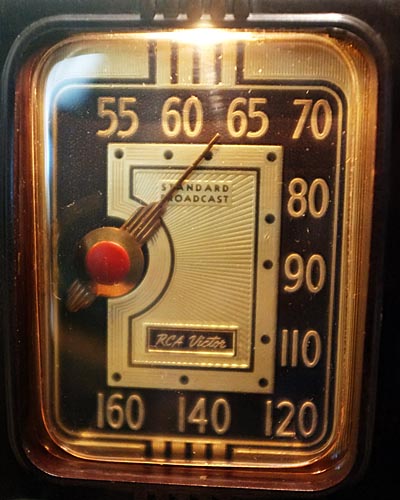
1940 RCA Model 1X AM Table Radio
I was given this RCA table radio, which I believe is a Model 1X. Although the labels are missing from the radio, it appears to be the 1940 model. The 1941 Model 1X2 has the Nipper dog logo on the dial scale.
Although very dirty, the Bakelite Art Deco case was in very good condition, with no chips or cracks. The knobs were missing, and the dial cover was extremely yellowed with age (not shown). I removed it and also set aside the dial pointer for safekeeping.
After removing the chassis, I checked it carefully, and could see that the electrolytic caps has been replaced, probably in the 1960's judging by the caps. I decided to bring it up slowly on a variable transformer and see if there was any life. At about 80 volts, I got audio and was able to tune in stations. At that point, I shut it down and proceeded to replace all the capacitors and installed a new power cord. I brought it up again to full power, and it played very well. The audio quality is very good.
I then proceeded to wash the cabinet in warm water and Dawn. When it dried, I begin polishing the cabinet with Novus #2. I followed this with a polishing and buffing with brown shoe polish. I installed a new dial cover and a set of non-original knobs.
The illuminated dial is very attractive, and the radio is a very good performer.
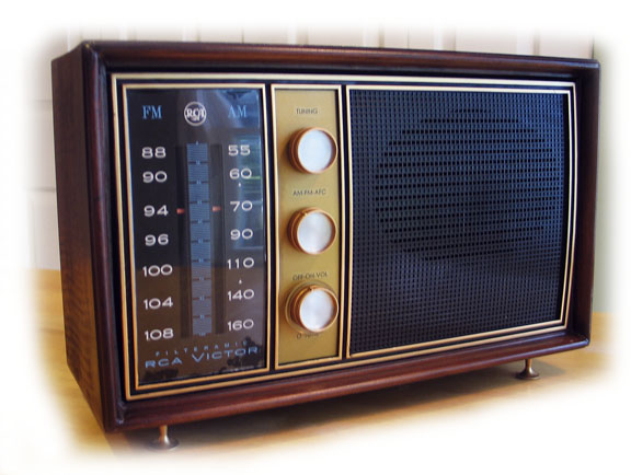
1963 RCA 3CR76 AM/FM Table Radio
I wish I had taken a before picture of this radio. It should have been tossed in a dumpster. It was given to me by a relative who thought I might be able to use the tubes in it. It has a printed circuit board chassis, which I find difficult to work on. Luckily I found a good schematic. The veneer was dried out, splitting, chipped and delaminating from the cabinet substrate. The dial indicator didn't move, and the radio didn't play. There was white paint on the front over the speaker enclosure. The feet were rusted. I removed the back to pull tubes and saw that the AM ferrite rod antenna had dried out and come apart. And, at some point, a radio serviceman had piggy-backed a multi-section electrolytic cap can to the original cap can mounted to the printed circuit board.
I pulled the chassis, and for some reason, I decided to see if I could get it to work. I tested the tubes and found three bad ones. I ordered replacements, and while I was waiting for the new tubes to arrive, I determined the tuning cord was slipping, so I restrung it and shortened the tension spring, which fixed that problem. I replaced all the paper caps. I removed the original cap can from the PC board along with its piggy backed replacement and installed new electrolytic caps of the proper values.
When the new tubes arrived, I installed them, then brought the radio up on the variac. It came to life and played well on FM. On AM, there was a lot of static and the signal cut in and out. I cleaned the rotors and stator fins, but no improvement. Careful inspection of the bottom of the PC board showed that the tuning gang assembly had broken loose from the traces. A hot soldering iron fixed that, and AM came in loud and clear. In fact, the radio performs better on AM than FM, which I have noticed is not unusual with early FM radios. I rebuilt the AM ferrite rod antenna with hot glue and new spacers made from a rubber grommet.
I removed all the old veneer from the top and sides of the cabinet. I then sanded the cabinet smooth with an orbital sander. I bought a package of veneer at Woodcraft. I attached the veneer to the cabinet substrate with carpenter's glue (yellow glue) and a hot iron. First I applied a coat of yellow glue to the top and sides of the cabinet and let it dry overnight. Then I applied a second coat of yellow glue to the cabinet, and a coat to the top and side pieces of veneer. To keep the veneer pieces from curling, I planked them to a large piece of cardboard with push pins along the edges of each piece. When the seoncd coat of glue was dry to the touch, I glued each piece of veneer to the cabinet using a hot iron. I used a piece of brown (kraft) paper between the iron and veneer. One side piece slipped during the gluing process and I had to remove it (not an easy job)and start over, but I finaly got the top and sides on properly. I let the veneer cure overnight. After about 48 hours, I notice a couple small bubbles of veneer where the glue wasn't holding, so I used the iron over the bubbles to re-attach the veneer. I think on my next veneering project, I would use three coats of glue on the subsrate and two on the veneer, especially on hardwood substate. The cabinet was so dried out that I think some of the glue just soaked in to the wood.
After the veneer was well cured, I stained the new veneer to match the rest of the cabinet, and applied three coats of lacquer, wet sanding between coats. After the third coat, I applied toner to even out the color, followed by several more coats of lacquer and wet sanding. The cabinet turned out well considering was it looked like in the beginning.
I spray painted the plastic front with black gloss, then applied a gold accent around the edges with gold spray paint. I masked out the areas I wanted to remain black. I painted the feet and knobs gold as well. When all was dried, I reassembled the radio. It turned out to be an interesting and challenging project, and was my first effort and re-veneering a cabinet.
1961 RCA 1-X-5JE
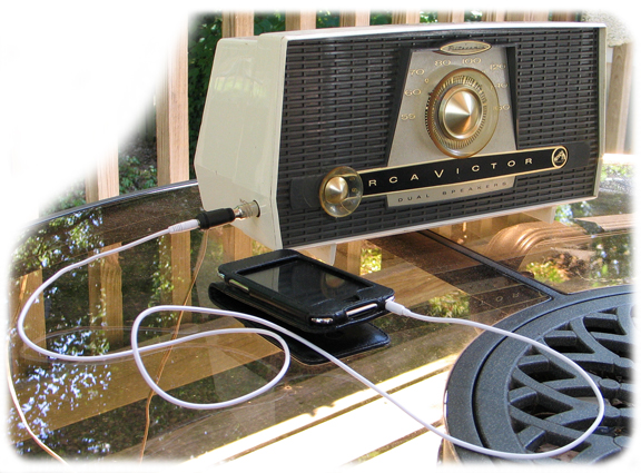
This c.1961 transitional AM broadcast 5-tube radio uses an early printed circuit board in place of a hand-wired chassis. I picked up this radio on Ebay a couple years ago because it had a phono input and dual speakers. I recently acquired an iPod Touch, so I pulled the radio off the shelf and opened it up. Repairs were simple. I replaced the three paper caps. The electrolytic cap had been replaced, so I left it in place. The ferrite rod antenna was broken loose from its holder, so I used a dab of hot glue to secure it. One of the two speakers was also loose, and had bent the 12AV6 tube. I refastened the speaker and straightened the pins on the 12AV6. All the tubes checked good, so I powered it up on a variac and it came right to life with nice sound. I then plugged the iPod into the phono input and that worked well also, so I put everything back together and now it's a nice deck radio when I want to listen to the iPod. With the iPod, I can listen to a variety of music with apps such as Pandora Radio or public radio as well as saved albums.
1957 RCA Globetrotter 7-BX-8J
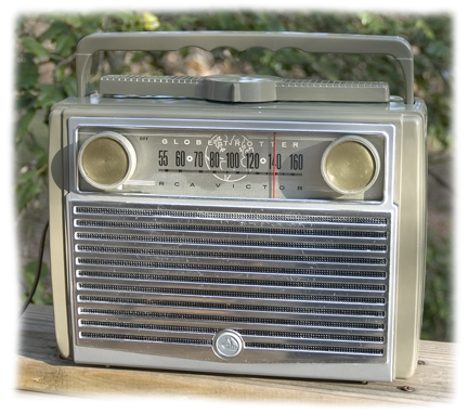 At right, a RCA Globetrotter 7-BX-8J Portable tube radio from around 1957. This radio uses a tube line-up similar to the Zenith Carousel above, but in a five tube chassis, adding 1T4's for the rf and if amps, a 1R5 for the converter, a 1U5 for the Detector-AVF-1st audio, and the 3V4 for the output. I bought the radio on EBAY as a working radio, but it was DOA when it arrived. Again, it only turned out to be a dead tube. Cosmetically, the radio was in excellent condition, except for the dial cover, which was cracked and yellowed. I made a new one from clear acetate and cleaned the radio with Novus plastic polish. Electrical restoration was somewhat of a challenge, as the electrolytic capacitors had been replaced, probably in the late 60's. Wires and components that had at one time been connected to the can were soldered together, along with the leads to the new caps, and taped with electrical tape and stuffed in the chassis. This radio has four electrolytic capacitors, so the mess was considerable. To sort it all out and restore some semblance of order, I first replaced all the paper caps to provide more room, then I mounted a new 5 lug terminal strip inside the chassis, and brought all the taped and soldered leads to the lugs, along with new electrolytic caps. I also replaced five out-of-tolerance resistors. The selenium rectifier had already been replaced with a diode, probably when the electrolytics were replaced in the 60's, so I left that alone. The speaker had a small tear, about 1/4", which I mended with white glue.
The radio played well, but was initially plagued with occasional static, like a thunderstorm in the background. This can be a symptom of silver mica migration in the capacitors that are embedded inside the IF transformers. Many of the radios made during the 1950's are starting to exhibit this problem. Although delicate and tedious, it is possible to remove the IF transformers, remove the mica wafer capacitors, and install new capacitors. Eventually I ended up removing the second IF transformer from this radio and replacing the mica capacitors, which corrected the problem. This was my first experience with rebuilding an IF transformer
Other than scratches on the speaker grill, which I was afraid to mess with much as the entire front assembly is easily bent, the radio looks almost new. I built a battery for it, but the space for the battery is just too small to build a battery that would last very long, so I just play it on AC.
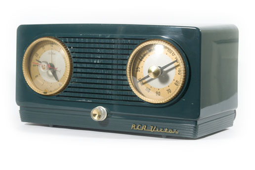
RCA Victor 4-C-533 ca. 1954
This was my first restoration project. I purchased this radio for $4.99 at an antique mall. Cosmetically, the radio was a basket case. However, with new caps and tubes, it powered right up and plays well. The cabinet has some deep scratches, the finial on the clock dial is missing, and the on/off knob under the clock is missing. Since this photograph was taken, I have found a finial and knob, so the radio is now complete.


